Logic Gates
Logic Gates: Overview
This topic covers concepts such as Types of Signals, Analogue Signals, Digital Signals, Logic Gates, Truth Table in Logic Gates, The NOT Gate, The OR Gate, The AND Gate, The NAND Gate, The NOR Gate, Basic Gate or Fundamental Gate, etc.
Important Questions on Logic Gates
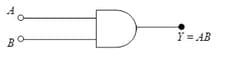
It is representing:
The same input signal is applied to both the (input) terminals of a given logic gate.
If the output is the(i) same as the (common) input signal
(ii) inverted with respect to the (common) input signal,
Identify the logic gate/s involved in each case.
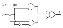
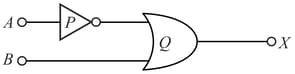
Identify the logic gates marked and in the given logic circuit.
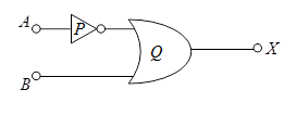
Identify the logic gates marked P and Q in the given logic circuit.
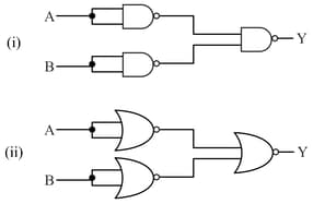
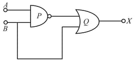
(i) Identify the logic gates marked P and Q in the given logic circuit.
The inputs A and B are inverted by using two NOT gates and their outputs are fed to the NOR gate as shown below.
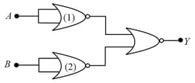
Analyse the action of the gates (1) and (2) and identify the logic gate of the complete circuit so obtained.
Name the two gates that can be used to form NOT gate.
What are the advantages of analogue signal?
What is a signal?
The human voice is an analogue signal while computers use digital signals.
Differentiate between analog signals and digital signals
Write the advantages of using digital signals over analogue signals.
Digital signals have ________ noise immunity compared to the analog signals.
Sine wave is a fundamental
The signals in which we use only two levels of voltage (represented by or ) are digital signals.
Out of these which is/are the property of the integrated circuit?
Write a short note on Integrated circuit.
Write a short note on digital signal.
How many NAND gates are required to form an AND gate?
To get output at for the given logic gate circuit the input values must be: