Uses of Boron and Aluminium and Their Compounds: Boron and Aluminium belong to the \({\rm{p}}\) block of the periodic table and are in the \({13^{{\rm{th}}}}\)...
Last Modified 13-04-2025

Harvest Smarter Results!
Celebrate Baisakhi with smarter learning and steady progress.
Unlock discounts on all plans and grow your way to success!

Uses of Boron and Aluminium and Their Compounds
April 13, 2025
Occurrence of Group 16 Elements: Different Elements, Properties, and Uses
March 31, 2025
Skin Derivatives: Epidermis, Dermis, Hair, Nail and Glands
March 30, 2025
Breathing in Other Animals: Meaning, and Respiratory Organs
March 23, 2025
Geometry and Locus: Loci of Geometrical Figures, Shapes
March 22, 2025
NCERT Book for Class 10 History 2025: Download PDF
February 27, 2025
CBSE Class 10 Notes 2025 – Check Here
February 27, 2025
CBSE Class 10 Maths Sample Paper 2025: PDF Download
February 27, 2025
NCERT Books For Class 10 Science 2025: Download PDF
February 20, 2025
NCERT Books for Class 10 2025: Download PDF
February 17, 2025
Interference of Light and Superposition Principle: One of the most important characteristics of light waves is their ability, under certain conditions, to interfere with one another. In physics, interference is defined as the superposition of waves that causes an increase or decrease in the amplitude of the resulting wave. Most people see optical interference on a daily basis but are unaware of what is causing it.
The light reflected from an oil film floating on water is one of the best examples of light interference. In this article, we will look at both constructive and destructive interference of light waves, as well as the causes of interference and superposition and some real-world examples and experiments that demonstrate this phenomenon.

The phenomenon when there is an apparent difference between the frequency at which light waves or sound waves leave a source and that at which they reach an observer, caused by the relative motion of the source of the wave and the observer is called Dopplers’ effect. This phenomenon was first observed 1842 by Austrian physicist Christian Doppler.
The light from a star, observed from the Earth, shifts toward the violet end of the spectrum (higher frequency or shorter wavelength) if the Earth and star are approaching each other and toward the red (lower frequency or larger wavelength) if they are receding from each other, called Red Shift. The Doppler effect is used to study the motion of stars, and it is important for the modern theory of the universe.
The apparent frequency is given by,
\(f_{o b s}=f_{s} \sqrt{\frac{1-\frac{v}{c}}{1+\frac{v}{c}}}\)
Where,
\(?\) is the velocity of the source. \(?\) is the velocity of light
The fractional change in the frequency in the Doppler effect is given by
\(\frac{{\Delta f}}{f} = \frac{{v\neg }}{c}\)
The formula given above is valid only when the speed of the source is small compared to that of light i.e \(v << c\)
Coherent light sources are those that emit a light wave with the same frequency, wavelength, and phase, or have a constant phase difference. When waves superimpose and the positions of maxima and minima are fixed, a coherent source produces sustained interference patterns.
Two independent sources are never coherent, or they cannot be considered coherent sources because all of the aforementioned factors cannot exist at the same time.
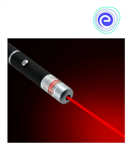
Example: Laser Light
Incoherent sources are light sources that emit waves with random frequencies and phase differences. In terms of frequency and phase difference, there is no relationship between the waves.
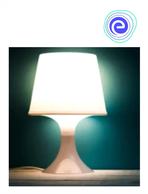
Example: Night Lamp
When two or more waves arrive at the same location, they superimpose on each other. When two waves come together, their disturbances are superimposed, this phenomenon is known as superposition.
Interference is the phenomenon of superposition of two waves to form the resultant wave of the lower, higher or same amplitude.
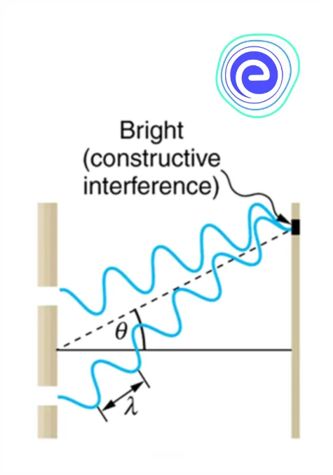
When there are two coherent sources of light of wavelength \((?)\), and the path difference at a point of interference from the two sources is \(??\), where \(?\) is an integer, then constructive interference occurs.
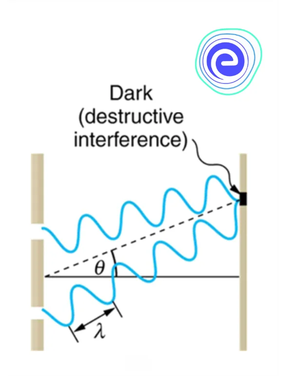
When there are two coherent sources of light of wavelength \((?)\), if the path difference at a point of interference from the two sources is \(??+?/2\), where ? is an integer, then destructive interference occurs.
The amplitude along \(y\)-axis of a sinusoidal wave traveling to the right along the \(x\)-axis is given by,
Let wave \(1\) is given by \(y_{1}(x, t)=A \cos (k x-\omega t)\)
Consider another wave of the same frequency and amplitude but with a different phase travelling to the right. and wave \(2\) is given by \(y_{2}(x, t)=A \cos (k x-\omega t+\phi)\)
Here \(A\) is the peak amplitude, \((\omega=2 \pi f)\) is the angular frequency of the wave, and \(k=2 \pi / \lambda\) is the wavenumber.
When the two waves superimpose, the resultant wave is given by:
\(y_{1}+y_{2}=A \cos (k x-\omega \mathrm{t})+A \cos (k x-\omega \mathrm{t}+\phi)\)
\(y_{1}+y_{2}=A \cos \frac{\phi}{2} \cos \left(k x-\omega \mathrm{t}+\frac{\phi}{2}\right)\)
We can see from the above equation that when the phase difference \((\phi)\) is odd multiple of \(\pi\), i.e. \((2 n+1) \pi\), then we get
\(y_{1}+y_{2}=0\)
Which is a destructive interference
Clearly the path difference for this will be \(n \lambda+\lambda / 2\)
when the phase difference \((\phi)\) is even multiple of \(\pi\), i.e. \(2 \mathrm{n} \pi\), then we get
\(y_{1}+y_{2}=2 A \cos (k x-\omega \mathrm{t})\)
Clearly the path difference for this will be \(n \lambda\)
Which is a constructive interference
As intensity is proportional to the amplitude, so at constructive interference, the amplitude doubles and intensity becomes four times.

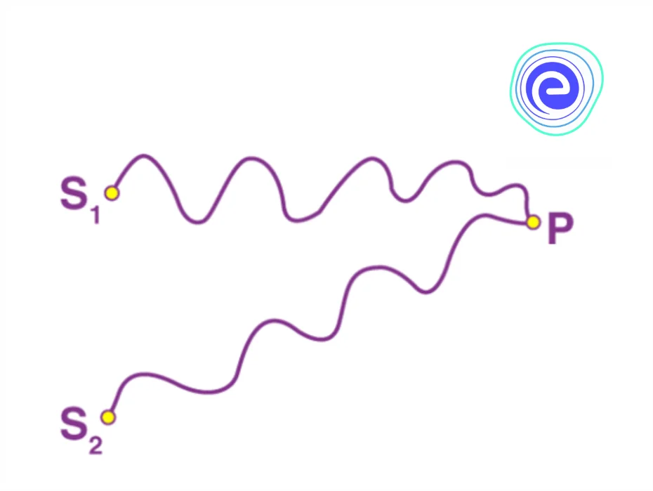
Young’s double-slit experiment helped to prove the wave nature of light and to understand the phenomenon of interference. The slits are separated from a screen or photodetector by a large distance ‘\(D\).’ Young’s original double-slit experiment used diffracted light from a single source, which was then passed through two additional slits to serve as coherent sources.
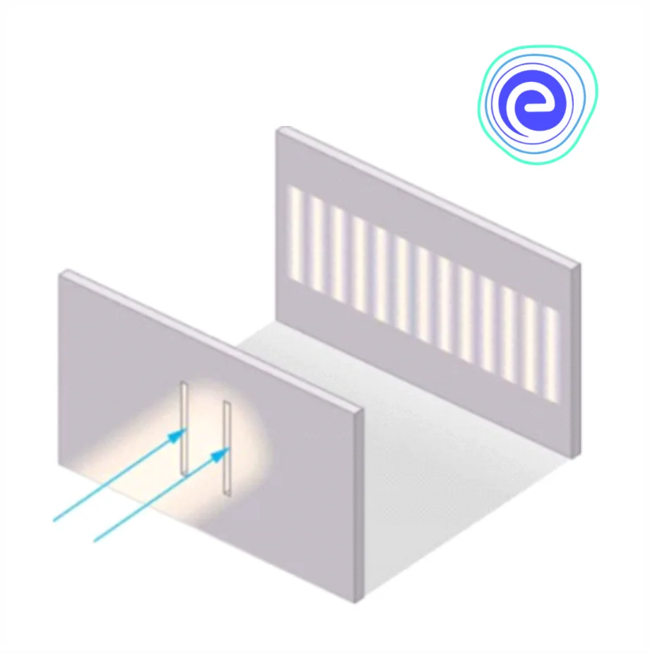
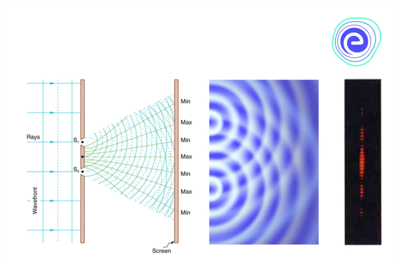
Alternate bright and dark bands of light called fringes are obtained on the screen suggesting constructive and destructive interference, given below are the ways in which the waves could combine to interfere constructively or destructively.
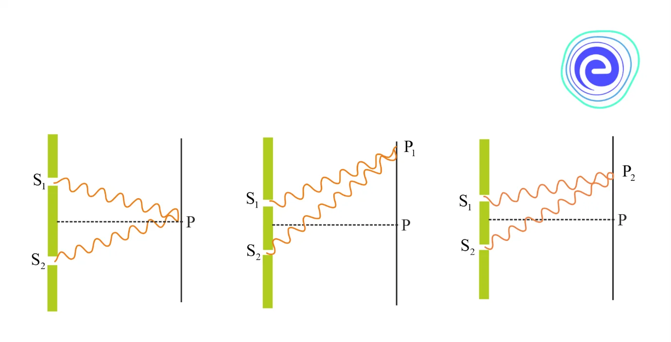
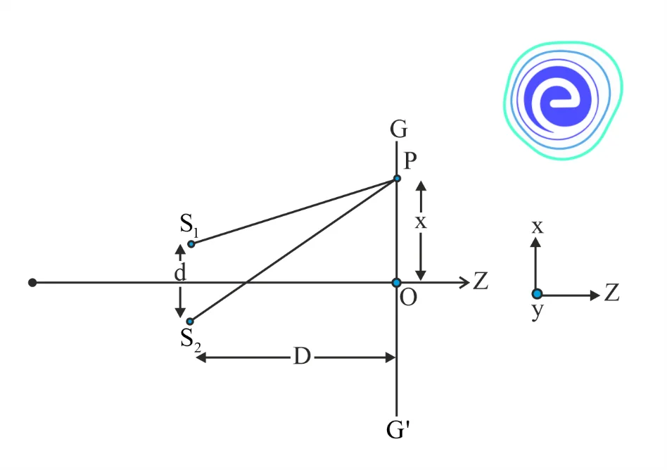
In the above diagram we can see that the two waves arrive at point \(\mathrm{P}\) by traversing the distances \(\mathrm{S}_{1} \mathrm{P}\) and \(\mathrm{S}_{2} \mathrm{P}\) respectively. Suggesting that they are superimposed with some phase difference at point \(P\).
\(\phi\) (phase difference)\(=\frac{2 \pi}{\lambda}\)*(Path diffrence)
\(\phi\) (phase difference)\(=\frac{2 \pi}{\lambda} *\left(\mathrm{~S}_{2} \mathrm{P}-\mathrm{S}_{1} \mathrm{P}\right)\)
From the diagram we can see that:
\(\left(\mathrm{S}_{2} \mathrm{P}\right)^{2}=\mathrm{D}^{2}+\left(x+\frac{d}{2}\right)^{2}\)
\(\left(\mathrm{~S}_{1} \mathrm{P}\right)^{2}=\mathrm{D}^{2}+\left(x-\frac{d}{2}\right)^{2}\)
\(\mathrm{~S}_{2} \mathrm{P}-\mathrm{S}_{1} \mathrm{P}=\frac{2 x d}{\mathrm{~S}_{2} \mathrm{P}+\mathrm{S}_{1} \mathrm{P}}\)
Since \(\mathrm{d}<<<<\mathrm{D}\), therefore \(\left(\mathrm{S}_{2} \mathrm{P}+\mathrm{S}_{1} \mathrm{P}\right)\) can be approximated to \(2 \mathrm{D}\), which gives
\(\mathrm{S}_{2} \mathrm{P}-\mathrm{S}_{1} \mathrm{P}=\frac{x d}{\mathrm{D}}\)
Now that we know the expression for the path difference and also know the conditions for constructive and destructive interference we can say:
Point \(P\) will be a bright fringe or of maximum intensity when the path difference is the integral multiple of wavelength \(\lambda \).
\(\frac{x d}{\mathrm{D}}=n \lambda\)
From here we get:
\(x_{n}=n \frac{\lambda \mathrm{D}}{\mathrm{d}}\)
Thus, bright fringes are obtained at:
\(x_{1}=\frac{\lambda \mathrm{D}}{\mathrm{d}}, x_{2}=2 \frac{\lambda \mathrm{D}}{\mathrm{d}}, x_{3}=3 \frac{\lambda \mathrm{D}}{\mathrm{d}}\)
As intensity \(I \propto A^{2}\)
Resultant intensity at this point is given by:
\(I=\left(A_{1}+A_{2}\right)^{2}=A_{1}^{2}+A_{2}^{2}+A_{1} A_{2} \cos \phi\)
\(I=I_{1}+I_{2}+2 \sqrt{I_{1}} \sqrt{I_{2}}\)
Similarly point \(\mathrm{P}\) will be a dark fringe or of minimum intensity when the path difference is the odd multiple of \(\frac{\lambda}{2}\).
\(\frac{x d}{\mathrm{D}}=(2 n+1) \frac{\lambda}{2}\)
Thus, dark fringes are obtained at:
\(x_{1}=\frac{\lambda \mathrm{D}}{2 \mathrm{~d}}, x_{2}=\frac{3}{2} \frac{\lambda \mathrm{D}}{\mathrm{d}}, x_{3}=\frac{5}{2} \frac{\lambda \mathrm{D}}{\mathrm{d}}\)
Resultant intensity at this point is given by:
\(I=I_{1}+I_{2}-2 \sqrt{I_{1}} \sqrt{I_{2}}\)
Fringe Width: The spacing between any two consecutive bright or two consecutive dark fringe is equal and gives us the fringe width.
Two consecutive bright fringes are located at:
\(x_{1}=\frac{\lambda \mathrm{D}}{\mathrm{d}}, x_{2}=2 \frac{\lambda \mathrm{D}}{\mathrm{d}}\)
Hence fringe width \(\beta=x_{2}-x_{1}=2 \frac{\lambda \mathrm{D}}{\mathrm{d}}-\frac{\lambda \mathrm{D}}{\mathrm{d}}=\frac{\lambda \mathrm{D}}{\mathrm{d}}\)
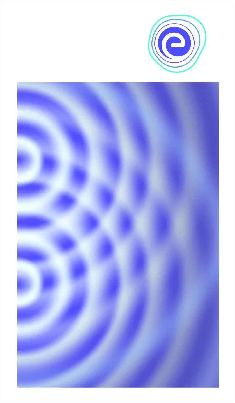
A wave propagating in a specific direction tends to spread out after passing through a narrow aperture (opening). Light being a wave, after passing through a single slit produces a diffraction pattern distinct from that produced by double slits or diffraction gratings.
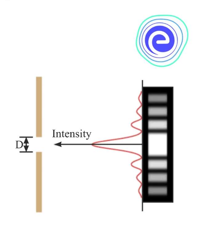
A single slit diffraction pattern is depicted in figure above. It’s worth noting that the central maximum is larger than the ones on either side, and that the intensity decreases quickly on either side.
Light diffracts in all directions through a single slit and can interfere constructively or destructively depending on the angle. \(d sin θ\) is found to be the difference in path length for rays coming from either side of the slit.
Observations show that the intensity has a central maximum at \(\theta=0\)
Other secondary maxima at \(\theta \approx(\mathrm{n}+1 / 2) \lambda \mathrm{a}\),
Minima (zero intensity) at \(\theta \approx \mathrm{n} \lambda / \mathrm{a}, \mathrm{n}=\pm 1, \pm 2, \pm 3, \ldots\).
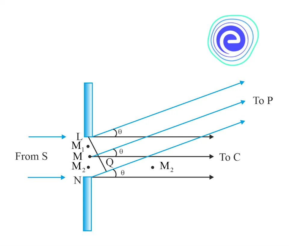
It is easy to observe why it has minima at these values of angle. Consider first the angle \(\theta\) where the path difference \(\mathbf{a} \theta\) is \(\lambda\). Then \({\theta} \approx \lambda / \mathbf{a}\).
Let us divide the slit into two equal halves \(\mathrm{LM}\) and \(\mathrm{MN}\) each of size \(\mathrm{a} / 2\). For every point \(\mathrm{M}_{2}\) in \(\mathrm{MN}\), there is a point \(\mathrm{M}_{1}\) in \(\mathrm{LM}\) such that \(\mathrm{M}_{2} \mathrm{M}_{1}=\mathrm{a} / 2\). The path difference between \(\mathrm{M}_{1}\) and \(\mathrm{M}_{2}\) at \(\mathrm{P}=\mathrm{M}_{2} \mathrm{P}-\mathrm{M}_{1} \mathrm{P}=\theta\, \mathrm{a} / 2=\lambda / 2\) for any chosen angle. This implies that the contributions from \(\mathrm{M}_{1}\) and \(\mathrm{M}_{2}\) are out of phase by \(180^{\circ}\) and cancel in the direction \(\theta=\lambda / \mathrm{a}\). Contributions from the two halves of the slit \(\mathrm{MN}\) and \(\mathrm{LM}\), therefore, cancel each other.
The equation \({\theta} \approx {\lambda}/a\) gives the angle at which the intensity falls to zero. One can similarly show that the intensity is zero for \(\theta=n \lambda \mathrm{a}\), with \(\mathrm{n}\) being any integer (except zero!).
we can see that the angular size of the central maximum increases when the slit width a decreases
Q.1. Two waves, one with an amplitude of \(1.5 \text {m}\) and the other with an amplitude of \(0.75 \text {m}\), are superimposed, with a destructive interference, what is the amplitude of the resulting wave?
Ans: Interference can be either constructive or destructive when two waves are superimposed. Because the interference is destructive in this case, our resultant amplitude will be the difference of the two given amplitudes.
So, our new amplitude will be \(1.5 \text {m} – 0.75 \text {m} = 0.75 \text {m}\).
Q.2. A parallel beam of light having a wavelength of \(500 \text {nm}\) falls on a narrow slit and the resulting diffraction pattern is captured on a screen \(1 \text {m}\) away. The first minimum is observed at a distance of \(2.5 \text {mm}\) from the centre of the screen. Calculate the width of the slit.
Ans:
Let wavelength of light beam, \(λ = 500 \text {nm}\)
Distance between screen from the slit, \(\text {D} =1 \text {m}\)
Also, \(x=2.5 \mathrm{~mm}=2.5 \times 10^{-3} \mathrm{~m}\)
Distance between the slits is \(\mathrm{d}\)
Distance of the first minimum from the centre of the screen can be obtained
As, \(\mathrm{n} \lambda=\mathrm{xd} / \mathrm{D}\)
\(\Rightarrow \mathrm{d}=\mathrm{n} \lambda \mathrm{D} / \mathrm{x}\)
For first minima, \(\mathrm{n}=1\)
\(\Rightarrow \mathrm{d}=1 \times 500 \times 10^{-9} \times 1 / 2.5 \times 10^{-3}=0.2 \mathrm{~mm}\)
Hence, the width of the slits is \(0.2 \mathrm{~mm}\).
When two or more sources of light illuminate the same point, the principle of superposition of waves applies. When we consider the intensity of light due to these sources at the given point, an interference term is added to the sum of the individual intensities.
Young’s double slit of separation \(d\) produces fringes of angular separation \(\lambda / \mathrm{d}\) that are equally spaced. A straight line connects the source, the midpoint of the slits, and the central bright fringe. A diffraction pattern with a central maximum is produced by a single slit of width a.
At angles of \(\pm \frac{\lambda}{a}, \pm 2 \frac{\lambda}{a}\) etc., the intensity drops to zero, with successively weaker secondary maxima in between.

Q.1. What is the phenomenon of interference?
Ans: Interference is the interaction of waves that are correlated or coherent (i.e. “interfere”), either because they come from the same source or have the same or nearly the same frequency.
Light, radio, acoustic, and surface water waves all exhibit interference effects.
Q.2. What is the phase difference and path difference?
Ans: The phase difference is the difference between the two waves’ phase angles. The difference in the paths traversed by the two waves is referred to as the path difference. The relationship between phase difference and path difference is straightforward. They are proportional to one another.
Q.3. What will happen when two identical waves are superimposed with destructive interference.
Ans: When two waves with destructive interference are superimposed, they cancel each other out. Because these two waves are identical, they will completely cancel each other out, resulting in the absence of a wave.
Q.4. What does Youngs double slit experiment explain?
Ans: Young’s double-slit experiment helped to prove the wave nature of light and to understand the phenomenon of interference.
Q.5. What is the definition of Fringe Width?
Ans: Fringe width, denoted by the symbol β, is the distance between two consecutive dark and bright fringes. The width of fringe is determined by the following factors:
(i) The wavelength of light.
(ii) The distance between the slits and the screen or slit separation.
Practice 10th CBSE Exam Questions
We hope this article on Interference of Light and Superposition Principle helps you in your study. Let us know if you face any difficulty. We will get back to you at the earliest.
Stay tuned to Embibe for the latest update of CBSE exams.